
You bought a spare VFD for your critical application. It is on the shelf in the MRO storeroom, still in the box, ready for the day the installed drive fails. That is good planning. Most plants do not even get that far.
But here is the question nobody asked: how long has that drive been sitting there unpowered? If the answer is more than a year, the spare may not be ready to save you. The DC bus capacitors inside that drive have been quietly degrading while it sat in storage. Without periodic reforming, the drive you are counting on for an emergency swap could fail on first power-up, turning one problem into two at the worst possible time.
What Is Happening Inside an Unpowered Drive
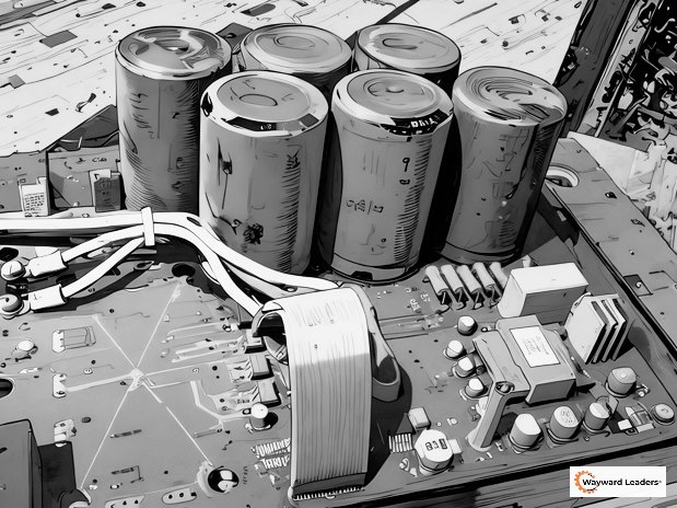
The electrolytic capacitors on the DC bus are the energy storage reservoir of the drive. They take the rectified DC output and smooth it into the stable voltage that the inverter section draws from to create the output waveform. On a 460 VAC drive, those capacitors hold approximately 650 VDC. They are also the components most affected by time.
Each electrolytic capacitor has an internal oxide layer that forms and maintains itself under voltage. This oxide layer is what gives the capacitor its insulating properties between the aluminum foil and the electrolyte. When voltage is present, the oxide layer stays intact and functional. When the drive sits unpowered, the oxide layer gradually deteriorates. The electrolyte chemistry shifts. The capacitor’s ability to hold voltage and absorb ripple current degrades.
This degradation is invisible from the outside. The drive looks fine. The packaging is intact. The display may even light up when you apply power. But the capacitors may no longer tolerate the full DC bus voltage. The result can be excessive leakage current, capacitor heating, premature failure, or in severe cases, a catastrophic capacitor failure on first energization that takes out the drive entirely.
The Timeline: When Does This Become a Problem?
The general industry guideline is straightforward.
Less than one year of shelf time: the drive can typically be energized normally without special procedures. The oxide layer is still intact enough to handle the soft charge sequence.
One to two years of shelf time: the drive should be powered up for at least one hour to allow the capacitors to reform their oxide layer under controlled conditions. The soft charge circuit inside the drive brings the DC bus up gradually, which gives the oxide layer time to re-establish itself.
Beyond two years: a gradual voltage increase using a variable AC source (variac) is recommended, with additional dwell time for each additional year of storage. The oxide layer has degraded enough that the full soft charge inrush may stress the capacitors beyond what they can safely absorb.
Five or more years: the drive may need professional evaluation or factory refurbishment. Some manufacturers, ABB among them, offer factory refurbishment services for drives with severely degraded capacitors. At this point, the capacitors may need physical replacement before the drive can be trusted in service.
These timelines are conservative guidelines, not hard cutoffs. The actual rate of degradation depends on storage temperature (cooler is better), humidity, and the specific capacitor chemistry used by the manufacturer. But the direction is always the same: time without voltage degrades the oxide layer.
How to Reform Capacitors in a Spare Drive
For drives stored one to two years, the process is simple. Connect the drive to its rated input voltage and allow it to sit powered on, but not running a motor, for a minimum of one hour. The soft charge circuit will bring the DC bus voltage up through the pre-charge resistors, limiting the inrush current while the oxide layer reforms. Monitor the drive during this period for any abnormal indications: unusual heat from the drive enclosure, audible noise from the capacitors (a buzzing or hissing sound), or fault codes related to the DC bus voltage.
For drives stored longer than two years, a more controlled approach is warranted. If you have access to a variable AC source (variac or variable transformer), bring the input voltage up gradually. Start at approximately 50% of rated voltage and hold for 30 minutes. Increase to 75% and hold for another 30 minutes. Then bring it to full rated voltage and hold for one hour. This controlled ramp gives the oxide layer time to reform incrementally without subjecting the degraded capacitors to full voltage stress all at once.
If a variable source is not available, consult the manufacturer’s documentation for their recommended reforming procedure. Some manufacturers publish specific reforming protocols in their installation or maintenance manuals, and these take precedence over general guidelines because they account for the specific capacitor types and voltage ratings used in that drive platform.
After reforming is complete, check the drive’s DC bus voltage reading. It should match the expected value for your input voltage (approximately 1.414 times the RMS line-to-line voltage). If the bus voltage is unstable, will not reach the expected level, or the drive faults during the reforming period, the capacitors may be too far degraded for field reforming and the drive needs professional evaluation.
Building Reforming Into Your Maintenance Program
The simplest approach: add a calendar-based task in your CMMS to reform every spare drive once per year. The task takes less than two hours per drive and requires nothing more than a power outlet and a torque wrench to verify connections before energizing. Schedule it during a planned maintenance window. Document the date, the drive serial number, and any observations during the reforming process.
For facilities with multiple spare drives, consider dedicating a small panel or receptacle in the storeroom specifically for periodic reforming. A 480V outlet on a dedicated breaker, properly labeled, makes the annual reforming task a five-minute setup instead of a logistical exercise involving extension cords and temporary connections.
The goal is to make reforming routine enough that it actually happens. A task that requires special equipment, special scheduling, and special expertise will get deferred indefinitely. A task that requires plugging in a drive and checking on it an hour later will get done. For more on building scheduled maintenance into your program, see our VFD Maintenance and Reliability Guide.
Capacitor Aging in Installed Drives
The same electrolytic capacitors that degrade on the shelf also age in service, though the mechanism is different. In an operating drive, capacitor life is driven by temperature and ripple current stress rather than oxide layer deterioration. Typical service life is 7 to 15 years depending on operating conditions.
The relationship between temperature and capacitor life follows the Arrhenius equation: for every 10 degrees Celsius increase in operating temperature above the manufacturer’s rated temperature, capacitor life is roughly halved. A drive running at 40 degrees Celsius ambient in a well-ventilated enclosure might get 15 years from its capacitors. The same drive in a 55-degree enclosure next to a boiler might get 5 years. This is why the thermal margin created by proper sizing and adequate cooling, covered in our VFD Installation Guide, has a direct, measurable impact on capacitor service life.
The DC bus voltage ripple measurement, recorded as part of the commissioning baseline, provides the trending data needed to detect in-service capacitor aging before it causes operational problems. Increasing DC bus ripple over time at the same load and ambient conditions indicates decreasing capacitance. For more on establishing that baseline, see our VFD Commissioning Guide.
Signs of Capacitor Problems
In spare drives after reforming, watch for excessive heat from the drive with no motor connected, DC bus voltage that will not stabilize at the expected level, or bus overvoltage or undervoltage faults during the reforming period. Any of these indicate capacitors that have degraded beyond what reforming can restore.
In installed drives, the warning signs develop more gradually: increasing DC bus voltage ripple trending upward over months or years, undervoltage faults at full load that did not occur previously, reduced ride-through capability during voltage sags (the drive trips on brief supply interruptions it used to ride through), and in severe cases, visible bulging or electrolyte leaking from the capacitor cans. For more on diagnosing undervoltage faults, see our VFD Troubleshooting Guide.
When these signs appear, the decision framework is straightforward: if the drive is relatively new and the capacitors are a replaceable module, capacitor replacement extends the drive’s life at a fraction of the cost of a new drive. If the drive is near the end of its design life and capacitor replacement is not economically justified, plan the drive replacement proactively rather than waiting for an unplanned failure.
Your Spare Drive Is an Insurance Policy
Like any insurance policy, it only pays off if it works when you need it. A simple annual reforming task, documented in your CMMS, keeps that policy valid. The day the installed drive fails and you need the spare, you want to pull it off the shelf knowing the capacitors are healthy, the oxide layer is intact, and the drive is ready to go.
For the complete maintenance framework including capacitor health trending, cooling fan scheduling, and CMMS integration, see our VFD Maintenance and Reliability Guide. For the full treatment of capacitor aging, the Arrhenius relationship between temperature and capacitor life, and the complete long-term reliability program, see Before the First Fault: A Field Guide to VFD Installation and Reliability. To build this level of reliability awareness across your maintenance team, see our training course.
Author: Dr. Carl Lee Tolbert, PhD, CMRP, Wayward Leaders LLC, waywardleaders.com
Frequently Asked Questions
What is VFD capacitor reforming?
Capacitor reforming is the process of applying voltage to an unpowered drive's DC bus capacitors to restore the internal oxide layer that degrades during storage. The oxide layer is what gives the capacitor its insulating properties, and without periodic reforming, a spare drive's capacitors may fail when power is applied for emergency service.
How often should I reform spare VFD capacitors?
Once per year is the standard recommendation. Add a recurring task in your CMMS tied to each spare drive's serial number. The task takes less than two hours per drive and requires no special equipment beyond a power outlet.
How long can a VFD sit on a shelf without being powered up?
Up to one year without concern. Between one and two years, the drive should be powered up for at least one hour to reform the capacitors. Beyond two years, a gradual voltage ramp using a variac is recommended. Beyond five years, the drive may need professional evaluation or factory refurbishment.
What happens if I do not reform capacitors in a spare VFD?
The oxide layer inside the electrolytic capacitors degrades over time without voltage. When you apply full voltage to a drive with degraded capacitors, the result can be excessive leakage current, overheating, premature failure, or catastrophic capacitor failure. The spare drive you were counting on fails when you need it most.
How do I know if my VFD capacitors need replacing?
In operating drives, watch for increasing DC bus voltage ripple, undervoltage faults at full load, reduced ride-through during voltage sags, or visible bulging or leaking on the capacitor cans. In spare drives, if the DC bus voltage will not stabilize during reforming or the drive faults during the process, the capacitors may be beyond field reforming.
Can I reform VFD capacitors without a variac?
For drives stored less than two years, yes. Simply connect the drive to its rated input voltage and let it sit powered on for one hour. The built-in soft charge circuit brings the bus voltage up gradually. For drives stored longer than two years, a variac is recommended because the oxide layer may be too degraded to handle even the soft charge inrush safely. Consult the manufacturer's reforming procedure for their specific recommendation.