
You bought a spare VFD for your critical application. It is in the MRO storeroom, still in the box, ready for the day the installed drive fails. That is good planning, and most plants never get that far.
What nobody tracks is how long that spare has gone without power. Past a year, the DC bus capacitors inside it have been degrading the whole time it sat there, and a spare that goes straight from the box to full line voltage can fail on first power-up. That turns 1 outage into 2, at the worst possible time, with the line down and production waiting. The fix is called reforming, and every manufacturer that publishes a procedure for it agrees on the shape: the longer the drive sat, the gentler and longer the first power-up has to be.
This guide is Step 6 in the VFD guide sequence, the shelf. It covers what happens inside an idle drive, how long each manufacturer lets a drive sit, how to pick and run the right reforming method, what a failed reform looks like, and how to build all of it into a maintenance program so you rarely need anything more than a yearly power-up.
What Happens Inside an Unpowered Drive
The electrolytic capacitors on the DC bus are the energy reservoir of the drive. The rectifier turns the incoming AC into DC, and the capacitors smooth it into the steady voltage the inverter section draws from to build the output waveform. On a 460 V drive those capacitors sit at roughly 650 V DC, and they are the parts in the drive most affected by time.
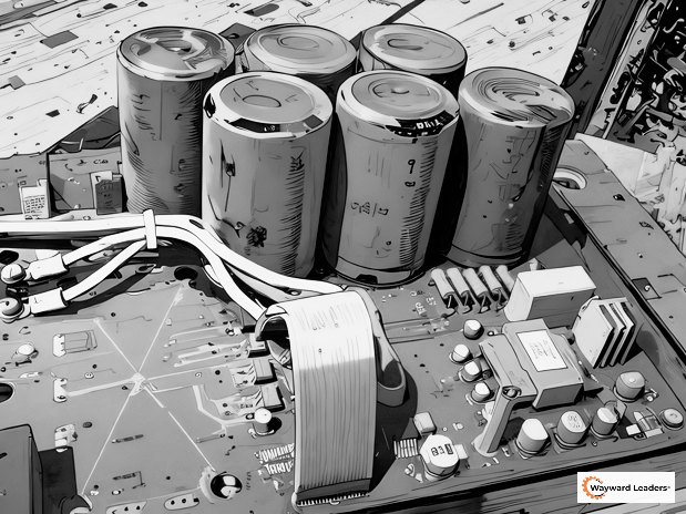
Each electrolytic capacitor has a thin oxide layer on its aluminum foil, and that layer is the insulation between the foil and the electrolyte. With voltage on it, the layer maintains itself. With the drive sitting unpowered, it slowly breaks down. Nothing shows on the outside. The packaging is intact, and the keypad may even light up when power goes on. What has changed is how much voltage the capacitors can hold without leaking current.
Put full bus voltage on a capacitor whose oxide layer has thinned and the leakage current runs high. That current makes heat inside the can, and the heat drives more leakage. A capacitor treated that way can run hot and fail early, or in the worst case fail outright on first energization. Reforming is just bringing the voltage up under control so the oxide layer can rebuild before the capacitors carry full load. ABB calls it re-aging, and Siemens and Beckhoff call it forming. It is the same job.
It Is Not Just the Storeroom
The capacitors do not care whether they sit in a box on a shelf or in an enclosure on the wall. Any drive that has gone more than a year without power is in the same spot as a spare:
- A seasonal irrigation or stormwater pump drive that sits off from fall to spring, and then sits a second season because the field was not planted.
- A standby fan or redundant pump drive that is wired and ready but has its disconnect open.
- A line that was mothballed and is coming back into production.
- A drive pulled from service, sent out for repair, and returned to the shelf as a spare.
- A drive in a new panel that was built, tested at the shop, and then sat on a jobsite through a long construction schedule.
The last one catches people. The panel shop powered it up once, a year and a half ago, and nobody has put voltage on it since. Treat every one of these exactly like a spare, with the same clock and the same methods.
The Clock Starts at the Build Date
The clock starts the last time the drive had power on it. For a drive that has never been installed, that means the day it was built, not the day you bought it. A spare bought 6 months ago may already have sat in a distributor’s warehouse for a year before it reached you. Siemens states it plainly for its cabinet drives: the storage period is counted from the date of manufacture, not the shipping date. Schneider says to check the manufacturing date before a first commissioning and reform any drive more than 12 months old.
So the first job on any spare is to find out when it was built. The date is on the type designation label or coded into the serial number.
On an ABB drive, a 10 digit serial such as 1173200725 breaks down as a country digit (1), the year (17, for 2017), the week (32) and a running number (00725). Older 8 digit serials put the year in 1 digit after the country digit, so 14250125 means built in Finland, 2004, week 25. The oldest 7 digit serials start with the year, so 3260034 means 2003, week 26. Siemens puts the date of manufacture in the serial number on the type plate. On other brands, the label usually carries a date code, and the manual or the manufacturer’s support line will tell you how to read it.
When you buy a spare, ask the distributor for the build date before it ships. A drive pulled from fresh stock buys you a full year on the shelf. A drive that sat in a warehouse for 2 years arrives needing the stepped method before it can run.
How Long a Drive Can Sit, by Manufacturer
Most manufacturers draw the first line at 1 year without power. Below it, no special steps. Between 1 and about 2 years, rated voltage with no load for a set time. Past that, a reduced or stepped voltage that comes up slower than the drive’s own soft charge circuit can manage.
| Manufacturer and drive | No reforming needed | Power on with no load | Reduced or stepped voltage |
|---|---|---|---|
| ABB (ACS380, ACS480, ACS800 and most others) | Under 1 year | 30 minutes, 1 to 2 years off | Over 2 years |
| ABB ACS580, ACH580, ACQ580, most ACS880 | Under 1 year | 30 minutes, 1 to 3 years off | Over 3 years |
| Siemens SINAMICS G120P cabinet units | Under 1 year | 1 hour, 1 to 2 years off | Over 2 years: form to the curve in the manual |
| Invertek Optidrive E3 | Up to 1 year | 1 hour, 1 to 2 years off | 2 to 3 years: 25, 50, 75 and 100 percent for 30 minutes each. Over 3 years: the same steps for 2 hours each |
| Yaskawa GA500 | Power at least once a year for 30 minutes | Over 2 years: ramp from 0 to rated over 2 to 3 minutes, then at least 1 hour with no load | |
| AutomationDirect GS20 | Under 1 year | 2 hours, motor disconnected | |
| Schneider Altivar Process ATV600 and ATV900 | 12 months at up to 50 C, 24 months at up to 45 C, 36 months at up to 40 C | 1 hour, no run command | |
| Toshiba VF-AS3 | 1 hour or more, once every 2 years in long term storage |
The power-on times run from 30 minutes to 2 hours across these makers, so the right time is the one printed for the drive you have, not a number someone remembers from a different brand. On the ABB drives, the line between the methods moves with the product family and the frame size, which is why ABB keeps a table of drive types next to its procedure.
Storage Temperature Moves the Line
Heat speeds up the breakdown of the oxide layer the same way it speeds up every other kind of capacitor aging. A spare stored in a hot mezzanine ages faster than one in a climate-controlled storeroom, and 2 manufacturers say so in their numbers.
Schneider ties the shelf limit on its Altivar Process drives directly to the warmest the storeroom gets: 12 months at a maximum of 50 C (122 F), 24 months at 45 C (113 F), and 36 months at 40 C (104 F). Beckhoff does the same on its AX8000 servo drives: reform every 5 years when stored below 25 C (77 F), every 3 years when stored above it. Toshiba sets its long term storage range for the VF-AS3 at minus 10 to 40 C with relative humidity at 90 percent or less, against a wider minus 25 to 70 C allowed for a month in shipping.
Yaskawa and Toshiba both draw the same distinction between shipping and storage. A wide temperature range is fine for the month a drive spends on a truck. A drive that will sit for years belongs indoors, dry, out of direct sunlight, away from corrosive gas, salt air, oil mist and dust, and somewhere without big temperature swings that cause condensation. AutomationDirect adds one more that sounds obvious and gets ignored: do not set the drive directly on the ground. Keep it on a shelf.
If your storeroom is not climate controlled, use the shortest limit the manufacturer gives, and power the spares every year regardless.
Choosing the Method
Once you know how long the drive has been without power, the method follows from the manufacturer’s table.
| Time without power | What to do |
|---|---|
| Under 1 year | Nothing special. Install and commission normally. |
| 1 to 2 years (1 to 3 on some ABB families) | Method 1: rated voltage, no load, for the maker’s time. |
| 2 to 3 years | Method 2 or 3: stepped AC voltage, or a current-limited DC supply. |
| Over 3 years | Method 2, 3 or 4 for longer, per the maker’s chart or table. |
| Unknown | Treat it as over 3 years until the build date proves otherwise. |
When the label is gone and nobody knows how long a drive sat, assume the worst. The slow method costs a few hours on a bench. The fast method on the wrong drive costs the drive.
Before You Start
The safety steps are the same for every method, and they matter more here than on a routine power-up, because the whole point is that you do not yet trust this drive.
- Clean and dry. The drive must be clean and dry, with no condensation, before you put any voltage on it. A drive that just came in from a cold truck or an unheated storeroom needs time to come up to room temperature first.
- Inspect it. Open the cover and look at the capacitors. Bulging tops, leaking electrolyte, white or brown residue, or rust on the cans mean replace, not reform. Do not energize a drive with visibly failed capacitors.
- No motor and no run. Disconnect the motor, or at least make sure no run command can reach the drive for the whole time it is reforming. Schneider calls this out specifically: verify that no run command can be applied before the hour is up.
- Lock out the normal supply when using an external circuit. For any external reforming circuit, disconnect the drive from every possible source, AC and DC, input and output. Lock the disconnect open. The drive’s own supply must never be switched on while a reforming circuit is connected.
- Prove it dead. Check your meter on a known source, then measure zero volts from the input terminals to ground and from the DC terminals to ground, then check the meter again.
- Plan the discharge. When reforming is done, switch the circuit off, wait at least 5 minutes for the bus to discharge (longer if the drive label says so), and measure the DC terminals near 0 V before you disconnect anything.
Method 1: Power It Up With No Load
For a drive inside the power-on window, the procedure is short. Make sure the motor is disconnected or no run command can reach the drive. Apply rated input power and leave it on for the time the manufacturer gives, from 30 minutes on an ABB to 2 hours on an AutomationDirect GS20. The drive’s soft charge circuit brings the bus up through its precharge resistors, which limits the inrush while the oxide layer rebuilds.
While it sits, stay near it. Check for unusual heat from the enclosure and listen for buzzing or hissing from the capacitors. A DC bus fault, a hot spot you can feel through the cover, or a smell means switch it off and investigate.
When the time is up, read the DC bus voltage on the keypad or with a meter on the DC terminals. With no load the bus charges to the peak of the line voltage, close to 1.414 times the line to line input, about 650 V DC on a 460 V supply and about 325 V DC on a 230 V supply. A bus that reads well under that, or drifts, is a warning. Write the reading down. It goes in the reforming log and it becomes the reference for next year.
Method 2: Bring the AC Voltage Up in Steps
For a drive past the power-on window, the voltage has to come up slower than the soft charge circuit will bring it. With a variable AC source, this means a variable transformer, or variac, rated for the drive’s input voltage and phases. With no load on the drive, the current it draws is small, so the variac does not have to be sized for the drive’s full input current.
Invertek gives the clearest table. For an Optidrive E3 off 2 to 3 years, apply 25 percent of rated voltage for 30 minutes, then 50 percent, 75 percent and 100 percent for 30 minutes each, 2 hours in total. Off more than 3 years, hold the same 4 steps for 2 hours each, 8 hours in total. On a 480 V drive the steps are 120, 240, 360 and 480 V.
Yaskawa does it as a ramp instead of steps on the GA500: bring the voltage from 0 to rated over 2 to 3 minutes, then hold at least 1 hour at full voltage with no load. Siemens points to a forming curve in the manual for its cabinet units past 2 years.
At the low steps the keypad may stay dark, or the drive may show an undervoltage alarm. That is expected. The point of the early steps is the capacitors, not the control board. Read the DC bus with a meter at each step if the keypad is not awake, and check that it climbs in proportion to the input.
Method 3: A Current-Limited DC Supply
ABB skips the variac on its drives past the power-on window and feeds the capacitors directly through the DC terminals, with the drive disconnected from everything else.
Set a regulated DC supply to 1.35 to 1.45 times the drive’s nominal AC voltage and hold the reforming current to 500 mA or less. On a 480 V drive that is about 648 to 696 V DC. On a 400 V drive, about 540 to 580 V DC. On a 240 V drive, about 324 to 348 V DC. A supply rated 0.5 to 1 A and adjustable to 1000 V DC covers all of these. If the supply has no adjustable current limit, put a 100 ohm, 500 W resistor in series and bring the voltage up gradually from 0. ABB is direct about the risk: too much DC voltage during reforming damages the capacitors.
How long it runs depends on how long the drive sat. ABB publishes a chart of reforming hours against years without power in its capacitor reforming instructions (document 3BFE64059629), with separate curves for the drive types that switch to an external circuit at 2 years and at 3 years. ABB’s older field service instructions for the ACS880-01 put it as a rule of thumb: 1 hour of reforming per year in storage, raising the voltage in steps of about 100 V if the supply cannot limit current. Use the chart in the current instructions for the drive in front of you, and treat the rule of thumb as a sanity check.
This is the same method used on spare capacitors and spare power modules, which ABB’s maintenance schedules list for reforming right alongside complete drives. Hitachi gives a separate procedure for a loose spare capacitor that has been stored more than 3 years: 80 percent of the capacitor’s rated voltage for 1 hour at room temperature, then 90 percent for 1 hour, then rated voltage for 5 hours.
Method 4: Diode Bridge or Series Resistors
For plants without a high-voltage DC supply, ABB gives 2 more circuits built from parts.
A diode bridge on the DC terminals. A rectifier fed from the AC line through a series resistor, with a 22 nF, 2000 V capacitor, feeds the drive’s DC terminals. The resistor ABB calls for is 220 ohm, 700 W for 200 to 240 V and 380 to 415 V drives, 470 ohm, 1200 W for 380 to 500 V, and 680 ohm, 1700 W for 525 to 690 V.
Resistors in the AC input lines. For a drive with no DC terminals, the resistors go in series with the input instead: 220 ohm, 700 W at 200 to 240 V, 220 ohm, 800 W at 380 to 415 V, and 470 ohm, 1200 W at 380 to 600 V. This matters because some small frames have no DC terminals at all. On the ABB ACS580 family in frames R1 to R3, and the ACS180 in frames R0 and R1, the series resistor method is the only external option once the drive is past the power-on window.
Both run for the time on ABB’s reforming chart. ABB also sells ready-made reformers for plants that do this often, and for a storeroom with a dozen or more spares, a purpose-built reformer pays for itself in setup time.
What a Failed Reform Looks Like
Heat from the drive with no motor connected, a DC bus that will not climb to or settle at the expected value, current on a DC supply that will not fall off as the capacitors charge, or overvoltage or undervoltage faults during the process all mean the capacitors are past what reforming can restore. Stop there. Do not try a second, faster pass to see if it clears.
The drive needs a capacitor replacement or a factory evaluation before it goes into service. It is far better to learn that on a bench in the storeroom on a Tuesday afternoon than during an outage with the line down. And if a spare fails its reform, the plant has just found out it has no spare, which is information somebody needs to act on now.
After a good reform, the first run under load still deserves attention. Yaskawa’s guidance after reforming is to wire the drive correctly and then watch for faults, overcurrent, motor vibration and speed differences during the first operation. A spare going into an emergency swap should get the same pre-energization checks as any new drive, set out in the VFD Commissioning Guide.
Keep a Reforming Log
Every reform gets a line in a log, kept with the spare or in the CMMS against its serial number. Over a few years the log shows which spares are healthy, which ones are drifting, and which ones nobody has touched.
| Field | What to record |
|---|---|
| Drive | Make, model, rating, serial number |
| Build date | From the label or serial |
| Last powered | Date of the previous reform or service |
| Method | Power on, stepped AC, DC supply, or resistor circuit |
| Time under power | Total, and each step if stepped |
| DC bus reading | At the end, and at each step if stepped |
| Observations | Heat, noise, faults, or none |
| Result | Pass, or failed and sent for repair |
| Next due | 1 year from today |
| Initials | Who did it |
Tape a tag on the box or the drive with the last powered date and the next due date. The person who grabs that spare at 2 a.m. should not have to look anything up to know whether it is safe to install.
Building Reforming Into Your Maintenance Program
The simplest approach is a calendar task in the CMMS to power every spare drive once a year, tied to each serial number. That keeps every spare under the 1 year line where no special procedure is needed. AutomationDirect, Yaskawa, Schneider and ABB field service all recommend powering an unused drive at least once a year anyway, so the yearly power-up satisfies every manufacturer in this guide.
For a storeroom with several spares, a dedicated reforming station turns the yearly task into a few minutes of setup. That means a receptacle or terminal block on its own breaker at each voltage you stock, labeled for reforming, with a way to read the DC bus and a place to set the drive down. A task that needs special equipment and special scheduling gets deferred. A task that means plugging a drive in and checking it an hour later gets done.
Fold the seasonal and standby drives into the same task. If an irrigation drive will sit off all winter, schedule a power-up before it sits a full year, or put the start of each season on the list as a reform event. The rest of the scheduled work for a drive, including the yearly spares task, is in the VFD Maintenance Guide. A spare also needs a current parameter backup to be useful in an emergency, covered in VFD parameter backups and restores.
Capacitor Aging in Installed Drives
The same capacitors age in service too, by a different mechanism. In a running drive, life is set by temperature and ripple current, as the electrolyte slowly dries out through the seal, rather than by the oxide breakdown of a drive on the shelf. Reforming does nothing for a capacitor that has worn out in service.
Manufacturers publish a design life for the DC bus capacitors, and every one of those numbers comes with conditions. Yaskawa gives 10 years for the V1000 at a yearly average ambient of 40 C, 80 percent load and 24 hour operation. Toshiba gives 10 years for the VF-AS3. ABB’s preventive maintenance program schedules DC bus capacitor replacement at 12 years from commissioning in normal conditions and 9 years for heavy duty loads or high ambient. A life number without its duty cycle is not a number.
Temperature is the lever. For every 10 C hotter, capacitor life roughly halves, and for every 10 C cooler it roughly doubles. A drive at 40 C in a well-ventilated enclosure might reach its full design life, and the same drive in a 55 C enclosure next to a boiler might get a third of it. That is why the thermal margin from correct sizing and cooling, covered in the VFD Sizing Guide and the VFD Installation Guide, shows up years later as capacitor life.
Several drives track this for you. The Yaskawa V1000 and GA500 keep a running estimate of capacitor life used, shown in the V1000 as monitor U4-05 as a percentage of the maintenance period, and other makers have similar monitors. Check them during the yearly PM.
The trend that catches in-service aging early is DC bus ripple, recorded in the commissioning baseline. Ripple climbing over time at the same load and ambient means capacitance is falling. On larger drives with a separate capacitor bank, ABB recommends measuring capacitance and ESR on the capacitors that run hottest, those farthest from the fan or nearest a failed one, with the caution that those readings show present condition and cannot predict remaining life. Other signs come later: undervoltage trips at full load that did not happen before, a drive that no longer rides through brief sags it used to, and in bad cases bulging or leaking cans. Sorting capacitor-related undervoltage from supply problems is in the VFD Troubleshooting Guide.
When those signs show up, the decision is mostly economic. On a larger drive with a replaceable capacitor bank, replacement extends its life for a fraction of a new drive. On a small drive, or one near the end of its design life and its manufacturer’s support, plan the replacement before it plans itself.
Your Spare Drive Is an Insurance Policy
Like any insurance policy, it only pays if it works when you need it. A yearly power-up, logged in the CMMS and tagged on the box, keeps the policy valid. When the installed drive fails and the spare comes off the shelf, you want to know the capacitors have seen voltage within the last year, the parameters are backed up, and the drive is ready to go.
New to drives, or want the basics of what the DC bus does first? Start with What Is a VFD?, Step 0 in the sequence. The full treatment of capacitor aging and the long-term reliability program is in Before the First Fault: A Field Guide to VFD Installation and Reliability. To build this kind of reliability habit across a maintenance team, see the training.
Frequently Asked Questions
What is VFD capacitor reforming?
Capacitor reforming is bringing voltage back onto the DC bus capacitors of a drive that has sat without power, under control, so the oxide layer inside the capacitors rebuilds before the drive carries load. ABB also calls it re-aging, and Siemens and Beckhoff call it forming. Without it, the capacitors can be damaged when the drive starts to operate.
How long can a VFD sit on a shelf before it needs reforming?
For most drives the line is 1 year without power, counted from the build date if the drive was never installed. ABB, Siemens, Invertek and AutomationDirect all draw it at 1 year. Some makers tie it to storage temperature: Schneider allows 12 months at up to 50 C, 24 months at up to 45 C and 36 months at up to 40 C on its Altivar Process drives, and Toshiba asks for power once every 2 years on the VF-AS3 in long term storage.
How long do you power up a spare VFD to reform the capacitors?
It depends on the maker and how long the drive sat. ABB says 30 minutes with no load for a drive off 1 to 2 years (1 to 3 years on the ACS580 family and most ACS880 types). Siemens, Schneider, Toshiba and Beckhoff say 1 hour. Invertek says 1 hour for 1 to 2 years. AutomationDirect says 2 hours for the GS20. Past the power-on window, the time climbs with the years off.
Can I reform VFD capacitors without a variac?
For a drive inside the power-on window, usually less than 2 years off, yes. The power-on method uses the drive's own soft charge circuit, so rated supply and no load is all it takes. Beyond that, the manufacturers call for a variable AC source, a current-limited DC supply, or a resistor circuit that holds the current down while the voltage comes up.
What voltage do you use to reform VFD capacitors with a DC power supply?
ABB uses a regulated DC supply set to 1.35 to 1.45 times the drive's nominal AC voltage, about 648 to 696 V DC for a 480 V drive, with the current held to 500 mA or less. If the supply has no current limit, ABB puts a 100 ohm, 500 W resistor in series and brings the voltage up gradually from 0. Too much DC voltage during reforming damages the capacitors.
Does a drive installed in a panel but switched off count?
Yes. The capacitors do not know whether they sit in a box or in an enclosure. A seasonal irrigation pump, a standby fan drive or a line that has been mothballed for over a year needs the same reforming as a spare on the shelf before it runs again.
How often should I reform spare VFD capacitors?
Once a year. AutomationDirect, Yaskawa, Schneider and ABB service all recommend powering an unused drive at least once a year, and a yearly task in the CMMS tied to each spare's serial number keeps every spare under the line where no special procedure is needed.
How do I know if my VFD capacitors need replacing instead of reforming?
In a spare, heat from the drive with no motor connected, a DC bus that will not climb to or settle at the expected value, or bus voltage faults during reforming mean the capacitors are past what reforming can restore. In a running drive, watch for DC bus ripple trending up, undervoltage trips at full load that never used to happen, and drives that no longer ride through short sags. Bulging or leaking cans mean replace, never reform.
Online start-up courses, filmed on real drives
One drive per course, filmed uncut with a clock on screen from first power to a saved backup. The install course is free, and the ABB ACS380 and ACS580 start-up course is open now.