
Very simply stated, a variable frequency drive controls the motor so that it may be run at very low speeds, very high speeds or anywhere in between. That definition comes from Larry Stanley, and I use it in my VFD class because it says what the drive is for before it says what is inside it.
You will hear the same box called an adjustable frequency drive (AFD), an adjustable speed drive (ASD), a variable speed drive (VSD), a frequency converter or an inverter. In the United States, the industry settled on variable frequency drive, or VFD, and that is the name this site uses.
The rest of this note is what every drive does, how it does it, how to check each part of it with a meter, and how to tell whether the motor in front of you needs one.
Want it all in one place? Watch the 7 minute video, or grab the free 14 page What Is a VFD? field guide. It has every figure and the meter checks in one download, no signup.
What every VFD does
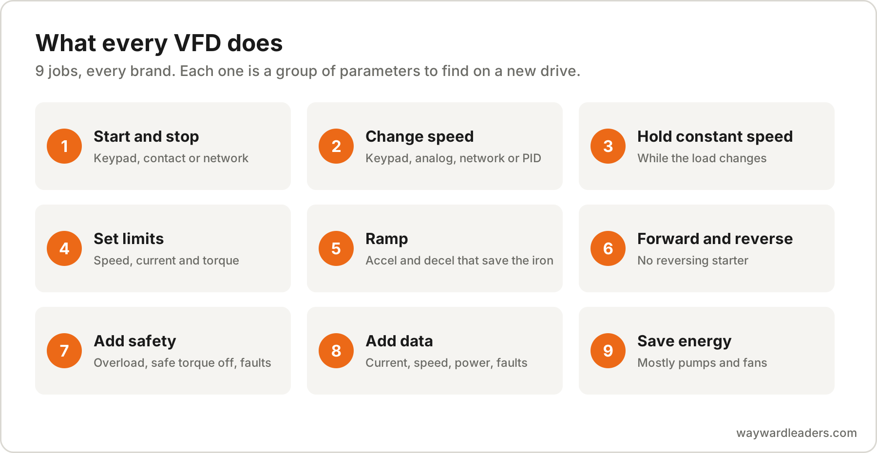
Strip away the brand, the keypad and the menu tree, and every drive on the market does the same short list of jobs. Knowing the list is how you learn a new drive fast, because each one is a group of parameters you will go looking for.
- Start and stop. From a keypad, a hardwired contact or a network command.
- Change speed. From a keypad, an analog signal, a network or a PID loop.
- Hold a constant speed while the load changes around it.
- Set limits. Minimum and maximum speed, current limit, torque limit.
- Ramp. How fast it accelerates and decelerates, which is what saves the coupling, the belts and the pipe.
- Run forward and reverse without a reversing starter.
- Add safety. Motor overload protection, safe torque off and a long list of faults that stop the motor before something breaks.
- Add data. Current, voltage, speed, power and a fault history, which is more information about the motor than most plants have anywhere else.
- Save energy on loads where the power falls with speed, which is mostly centrifugal pumps and fans.
The 3 sections inside every drive
Open any standard 6 pulse drive from any maker and you will find the same 3 sections in the power circuit, AC to DC to AC. Knowing them is what lets you troubleshoot a drive you have never seen before.
- The input converter. A diode bridge on the input terminals, usually marked L1, L2 and L3 or R, S and T. It turns incoming AC into pulsing DC. On most drives it is a 6 pulse bridge, which is also where a drive’s harmonics come from, because it pulls current from the line in short, sharp gulps instead of a smooth sine wave.
- The DC bus. A bank of capacitors that smooths that DC and stores it. On a 480 V supply the bus sits at about 650 VDC with the drive running, roughly 1.35 times the line voltage, and a little higher at light load. On a 230 V supply it is about 310 VDC. Many drives also carry a DC choke here to soften the input current.
- The output inverter. Six IGBTs on the output terminals, marked T1, T2 and T3 or U, V and W. They switch the DC bus onto the motor leads and off again, thousands of times a second, to build a new AC waveform at whatever frequency the drive is commanded to make.
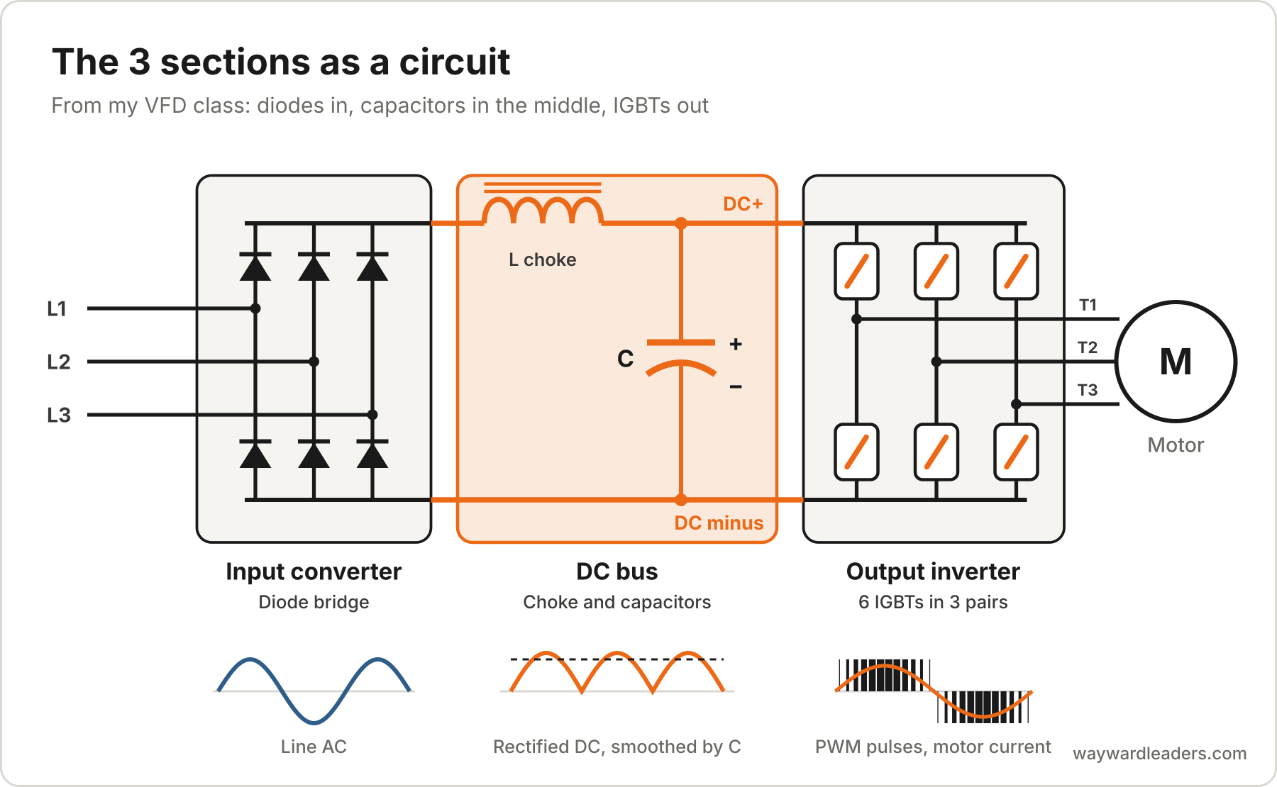
The 6 IGBTs sit in 3 pairs, one pair for each motor lead. The top one connects its lead to DC+ and the bottom one to DC minus, and the drive never turns both on at once, because that would short the bus.
The control board watches all 3 and trips the drive when something goes outside its limits. Most of the fault codes you will ever read are that board telling you which section it was protecting.
How the drive makes speed
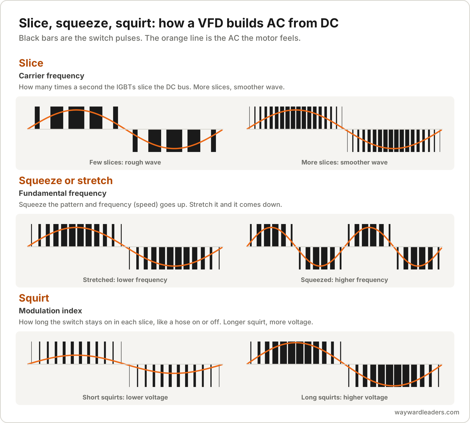
The inverter does not make a smooth sine wave. It makes square pulses of full bus voltage and varies how wide they are, and in the motor’s windings those pulses add up to a current that looks close to a sine wave. That is pulse width modulation, PWM. What comes out is shaped by 3 settings, and I teach them as slice, squeeze and squirt:
- Slice: the carrier frequency, or switching frequency. How many times a second the IGBTs slice the DC bus into pulses, commonly somewhere from 2 to 16 kHz. It sets the quality of the output waveform. More slices make it smoother and quieter at the motor, and they make the drive run hotter and push more noise into the cable and bearings.
- Squeeze or stretch: the fundamental frequency. Squeeze the pattern of pulses together and the output frequency goes up. Stretch it out and the frequency comes down. It sets the output frequency, and that sets the motor speed.
- Squirt: the modulation index. How long the switch stays on in each slice. Think of a water hose that is either on or off: a longer squirt in each slice puts out more, a shorter one less. It sets the magnitude of the output voltage.
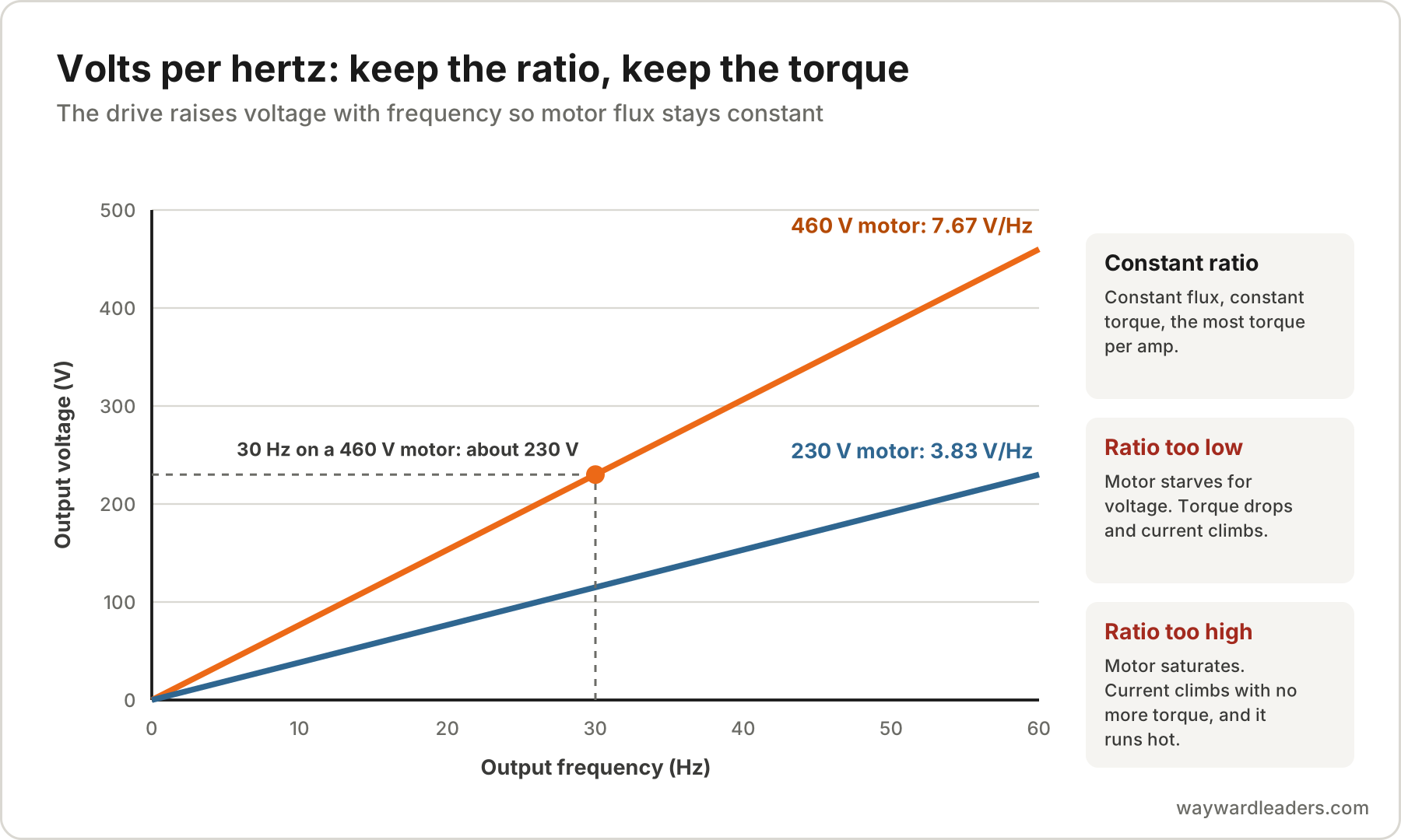
The drive moves the voltage and the frequency together so the motor’s magnetic flux stays right. A 460 V, 60 Hz motor runs at about 7.67 volts per hertz (460 divided by 60), so at 30 Hz the drive gives it about 230 V. A 230 V motor runs at about 3.83 volts per hertz. That is V/Hz control, and here is why the ratio matters:
- A constant V/Hz ratio gives constant motor flux, and constant flux gives constant torque and the most torque per amp.
- Too low a ratio starves the motor for voltage. Flux drops, torque drops, and the current climbs trying to make up for it.
- Too high a ratio saturates the motor. Current climbs with no more torque to show for it, and the motor overheats.
Sensorless vector and closed loop vector modes do the same job with a motor model and, for closed loop, an encoder, and they hold torque better at low speed. All of them depend on accurate motor nameplate data going into the drive.
How to check each section with a meter
When a drive is dead or won’t come out of a power fault, the 3 sections give you an order to work in. Lock out and tag out first, and treat the bus as live until you have measured it.
- Prove the bus is dead. Wait the discharge time printed on the drive’s label, then measure DC voltage across the DC+ and DC minus terminals. Do not open anything else until that reads near zero. Bus capacitors can hold a lethal charge long after the line is opened.
- Check the input converter. With the meter on diode test, read from each input terminal to DC+ and to DC minus, both directions. A good diode reads a forward drop of a few tenths of a volt one way and open the other. The point is that all 3 phases read alike. One that reads short or open is your failed diode.
- Check the output inverter. Do the same from each output terminal to DC+ and DC minus. Again, all 3 phases should match. A shorted IGBT usually shows up as a near zero reading in both directions on one phase.
- Check the bus under power. Restore power and read the bus. It should sit near 1.35 times the line voltage at idle. A bus that is low, or that ripples badly under load, points at a missing input phase or tired capacitors.
- Check the output under load. With the motor running, read the output current on all 3 phases. They should be balanced within a few percent. A drive that reads balanced at its output and still trips is usually telling you about the motor, the cable or the load, not itself.
Drive makers publish their own test values and test points, and the manual for the drive in front of you wins over anything general. The order above is what stays the same from brand to brand.
When a VFD is the right call
There are only 4 kinds of load, even though there are thousands of versions of them: constant torque, constant horsepower, variable torque and impact. The kind decides what the drive has to do.
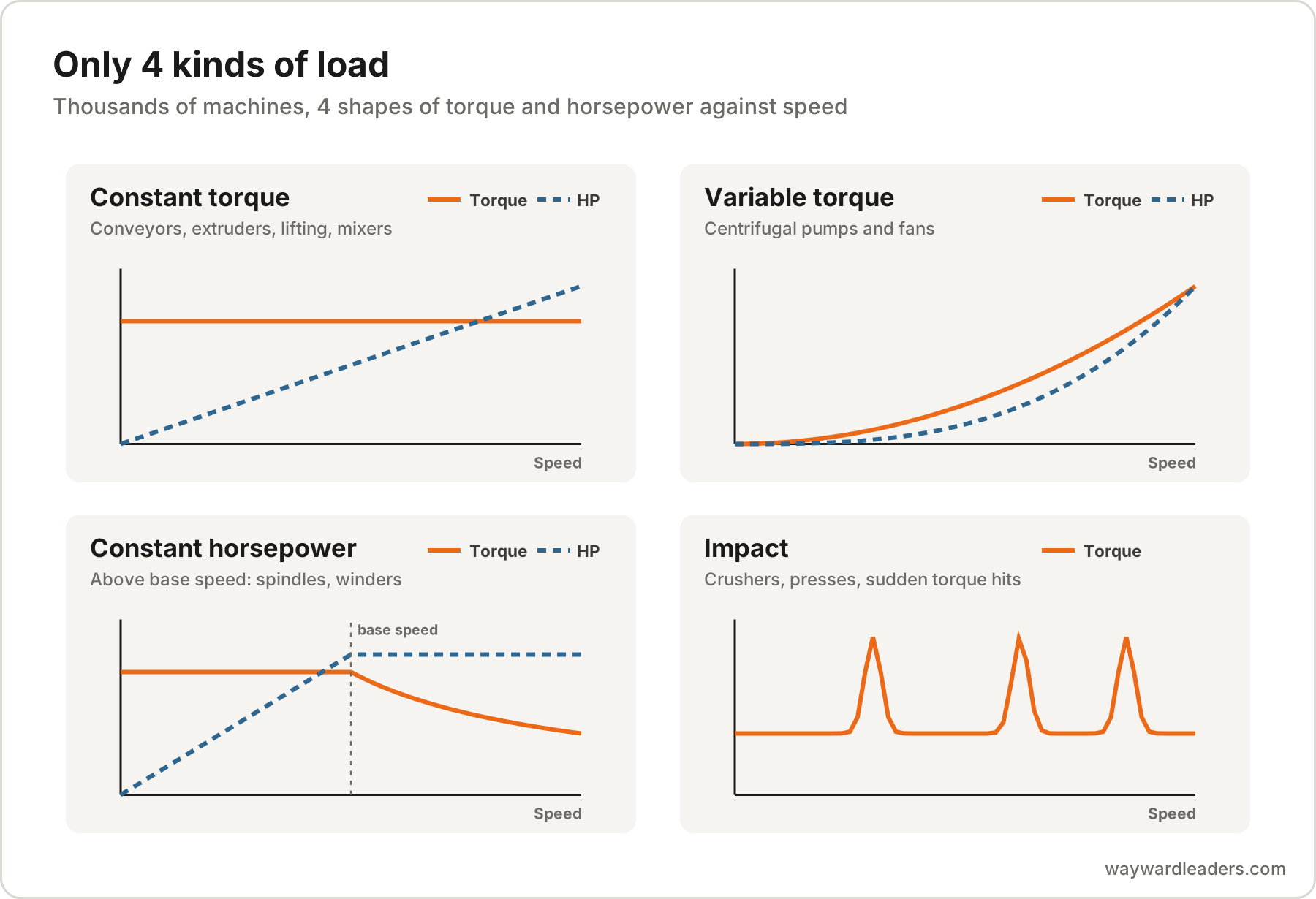
- Variable torque, centrifugal pumps and fans. Power falls with roughly the cube of speed, so 80 percent speed needs about half the power. This is where drives pay for themselves, and the note on what a VFD actually saves works through why the load decides the savings.
- Constant torque, conveyors, extruders, lifting equipment, mixers. Torque stays the same at every speed and horsepower rises with speed. Drives earn their place here on control, ramps and starting torque more than on energy.
- Constant horsepower, running above base speed. Spindles and winders, where torque falls as speed climbs.
- Impact loads. Crushers, presses and anything that hits the motor with sudden torque. These need a drive sized for the peaks, not the average.
A drive is the wrong call when the motor runs at full speed all the time and only needs a gentler start. A soft starter does that with less money and complexity. It cannot control speed, it works best on light to medium inertia, it is bound by its duty cycle and it gives up torque at start, so it only fits the jobs that need none of those. The comparison is in soft starter vs VFD.
What a drive costs the motor and the building
A drive does all the good a soft starter does and a lot more, and it brings a bill with it: it can destroy motors, it generates heat, it puts harmonics on the supply, and it adds complexity. None of those are reasons to avoid drives. They are reasons the install matters more than the drive brand.
Its fast pulses put voltage spikes on the motor windings that a line started motor never saw, which is why motor ratings matter on drive jobs. The note on inverter duty motors covers what to buy. The same pulses push common mode current through the motor bearings when the cable and grounding don’t give it a way home, covered in shaft grounding rings and bearing currents. And the cable between the drive and the motor stops being ordinary wire, covered in VFD cable.
The VFD Installation Guide walks through the install in order. The free What Is a VFD? field guide puts this note in one download, and the free What Is a VFD class and the free First Power course, which teaches the checks before the first power up, are both at The Tolbert School.
Frequently Asked Questions
What is a VFD in simple terms?
Very simply stated, a variable frequency drive controls the motor so that it may be run at very low speeds, very high speeds or anywhere in between. It does that by changing the frequency and voltage the motor sees. You will also hear it called an adjustable frequency drive (AFD), an adjustable speed drive (ASD), a frequency converter, an inverter, or just a drive.
How does a VFD work?
Every drive does it in 3 sections. The input converter, a diode bridge, turns incoming AC into DC. The DC bus, a bank of capacitors, holds that DC steady. The output inverter, a set of IGBTs, switches the DC on and off thousands of times a second to build a new AC waveform at whatever frequency the drive is told to make, with the voltage raised and lowered along with it.
Why does a VFD keep a constant volts per hertz ratio?
A constant V/Hz ratio keeps the motor's magnetic flux constant, and constant flux gives constant torque and the most torque per amp. Too little voltage for the frequency starves the motor, cuts its torque and drives the current up. Too much saturates it, which raises current without adding torque and overheats the motor. A 460 V, 60 Hz motor runs at about 7.67 V/Hz, and a 230 V motor at about 3.83 V/Hz.
What is the DC bus voltage on a 480 V VFD?
About 650 VDC with the drive running, and a little higher at light load. It is roughly 1.35 times the incoming line to line voltage. The bus stays charged after power is removed, so prove it dead with a meter at the DC bus terminals before touching anything inside the drive.
What is the difference between a VFD and a soft starter?
A soft starter only softens the start, then lets the motor run at full speed on the line. It cannot control speed, it works best on light to medium inertia, and it gives up torque at start. A VFD does everything a soft starter does and also controls speed, ramps and torque the whole time the motor runs. If the process needs speed control, it needs a drive.
Online start-up courses, filmed on real drives
One drive per course, filmed uncut with a clock on screen from first power to a saved backup. The install course is free, and the ABB ACS380 and ACS580 start-up course is open now.